
CEH Scanner V1 — Hardware Design
Full engineering documentation. Schematics, PCB block diagram, pinout, BOM, and design rationale. We publish this because transparency builds trust — you should know exactly what's inside the device plugged into your vehicle.
📐 System Architecture
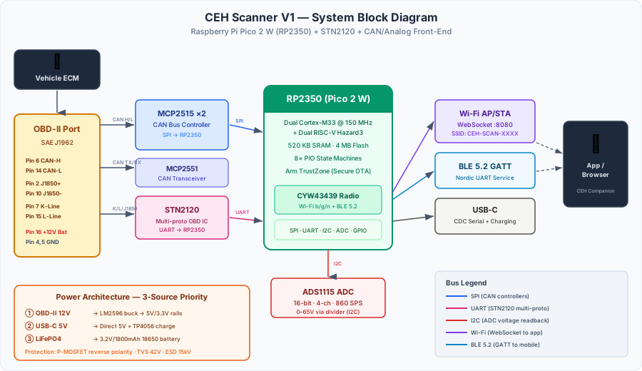
View text-based block diagram (accessibility)
┌──────────────────────────────────────────────────────────────────────────────┐
│                       CEH Scanner V1 — Block Diagram                        │
├──────────────────────────────────────────────────────────────────────────────┤
│                                                                              │
│  ┌──────────────┐     ┌──────────────────────────────────────────────────┐   │
│  │  OBD-II Port  │     │          Raspberry Pi Pico 2 W (RP2350)          │   │
│  │  (J1962 Male) │     │  ┌──────────────┐  ┌──────────────────────────┐ │   │
│  │               │     │  │ Dual Cortex-M33│  │    CYW43439 Radio       │ │   │
│  │  Pin 6 ──CAN-H├─┐   │  │ 150 MHz       │  │  Wi-Fi 802.11 b/g/n    │ │   │
│  │  Pin 14──CAN-L│ │   │  │ + RISC-V co-  │  │  Bluetooth 5.2 (BLE)   │ │   │
│  │  Pin 7 ──K-Line├─┤   │  │   processors  │  │  On-board antenna      │ │   │
│  │  Pin 2 ──J1850├─┤   │  │ 520KB SRAM    │  └──────────────────────────┘ │   │
│  │  Pin 16──+12V ├─┤   │  │ 4MB Flash     │                               │   │
│  │  Pin 4/5─GND  ├─┤   │  └──────────────┘  SPI / I2C / UART / PIO       │   │
│  └──────────────┘ │   └────────┬─────────────────────────────────────────┘   │
│                    │            │                                             │
│  ┌─────────────┐  │   ┌────────┴────────────────────────────────────────┐    │
│  │ CAN Bus     │  │   │              Peripheral ICs                      │    │
│  │ Transceiver │◄─┤   ├─────────────────────────────────────────────────┤    │
│  │             │  │   │                                                  │    │
│  │ MCP2515     │  │   │  ┌──────────┐  ┌──────────┐  ┌───────────────┐ │    │
│  │ (Controller)│  │   │  │ ADS1115  │  │ STN2120  │  │ LM2596 Buck   │ │    │
│  │ MCP2551     │  │   │  │ 16-bit   │  │ Legacy   │  │ 12V→5V→3.3V  │ │    │
│  │ (Transceiver│──┘   │  │ ADC 4-ch │  │ Protocol │  └───────────────┘ │    │
│  └─────────────┘      │  └──────────┘  └──────────┘                     │    │
│                        │                                                  │    │
│  ┌─────────────┐      │  ┌──────────┐  ┌──────────┐  ┌───────────────┐ │    │
│  │ USB-C Port  │      │  │ TVS      │  │ Status   │  │ LiFePO4 18650│ │    │
│  │ (J2534 +    │      │  │ Diodes   │  │ LEDs (4) │  │ 3.2V 1800mAh│ │    │
│  │  FW update +│      │  │ ESD 15kV │  │ P/L/D/B  │  │ + TP4056     │ │    │
│  │  charging)  │      │  └──────────┘  └──────────┘  │ USB-C charge │ │    │
│  └─────────────┘      │                               └───────────────┘ │    │
│                        │  ┌──────────┐  ┌──────────────────────────────┐ │    │
│  ┌─────────────┐      │  │ microSD  │  │ Aux Sensor Header (4-pin)   │ │    │
│  │ External    │      │  │ Card Slot│  │ Ch2: Wideband O2 (0-5V)    │ │    │
│  │ Sensor HDR  │──────┤  │ Push-Push│  │ Ch3: EGT/Boost (0-5V)     │ │    │
│  │ (4-pin JST) │      │  │ FAT32   │  │ + 5V ref + GND             │ │    │
│  └─────────────┘      │  │ ≤32 GB  │  └──────────────────────────────┘ │    │
│                        │  └──────────┘                                   │    │
│                        └─────────────────────────────────────────────────┘    │
│                                                                               │
│  Protection: Reverse polarity (P-MOSFET) │ 42V transient (TVS)               │
│  Battery: LiFePO4 18650 (2000+ cycles) │ Power: 12V OBD-II OR USB-C OR batt  │
│  Storage: microSD (data logs, firmware, PID configs, gauge layouts)           │
│  Operating: -20°C to +65°C │ PCB: Designed in Flux.ai, fab by JLCPCB        │
└───────────────────────────────────────────────────────────────────────────────┘
OBD-II Connector Pinout (J1962)
Standard 16-pin SAE J1962 connector. The CEH Scanner uses pins 2, 4, 5, 6, 7, 10, 14, 15, and 16. Unused pins are left floating (no internal pullups).
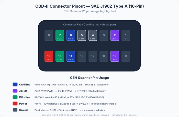
| Pin | Signal | Protocol | CEH Usage | Active |
|---|---|---|---|---|
| 1 | Manufacturer discretionary | — | Not connected | — |
| 2 | J1850 Bus+ | SAE J1850 VPW/PWM | GM/Ford legacy vehicles via STN2120 | ✓ |
| 3 | Manufacturer discretionary | — | Not connected | — |
| 4 | Chassis ground | All | Signal ground reference | ✓ |
| 5 | Signal ground | All | Signal ground reference | ✓ |
| 6 | CAN High (CAN-H) | ISO 11898 | Primary CAN bus via MCP2515/MCP2551 | ✓ |
| 7 | K-Line | ISO 9141-2 / ISO 14230 | European/Asian vehicles via STN2120 | ✓ |
| 8 | Manufacturer discretionary | — | Not connected | — |
| 9 | Manufacturer discretionary | — | Not connected | — |
| 10 | J1850 Bus− | SAE J1850 PWM | Ford PWM negative line via STN2120 | ✓ |
| 11 | Manufacturer discretionary | — | Not connected | — |
| 12 | Manufacturer discretionary | — | Not connected | — |
| 13 | Manufacturer discretionary | — | Not connected | — |
| 14 | CAN Low (CAN-L) | ISO 11898 | Primary CAN bus via MCP2515/MCP2551 | ✓ |
| 15 | L-Line | ISO 9141-2 | Init line for older K-Line vehicles | ✓ |
| 16 | +12V Battery | All | Power input → LM2596 buck (3.3V/5V) | ✓ |
Key Components
Raspberry Pi Pico 2 W (RP2350) — Main MCU
DigiKey SC1633 · $7.00/unit · In-stock
| MCU | RP2350 — Dual Arm Cortex-M33 @ 150 MHz + dual RISC-V Hazard3 co-processors |
| SRAM | 520 KB on-chip |
| Flash | 4 MB on-board QSPI |
| Radio | CYW43439 — Wi-Fi 802.11 b/g/n (2.4 GHz) + Bluetooth 5.2 (BLE) |
| Antenna | On-board PCB antenna (no external antenna needed) |
| USB | USB 1.1 Host/Device (native on RP2350) |
| PIO | 3× PIO blocks (12 state machines) — hardware-level protocol timing |
| GPIO | 26 multi-function (SPI ×2, I2C ×2, UART ×2, PWM, ADC) |
| Security | Arm TrustZone, secure boot, signed firmware, OTP fuses |
The Pico 2 W is chosen for its $7 price point, CYW43439 integrated radio (Wi-Fi + BLE on one IC), PIO state machines (bit-banging CAN/J1850 timing in hardware), Arm TrustZone for secure OTA updates, and massive community + SDK support. Prototype with Wokwi Pi Pico Simulator before hardware.
MCP2515 + MCP2551 — CAN Bus
| MCP2515 | Stand-alone CAN controller, SPI interface |
| MCP2551 | High-speed CAN transceiver (ISO 11898) |
| Bus Speed | 250 kbps / 500 kbps (auto-detect) |
| Channels | Dual CAN (2× MCP2515/2551 pairs) |
| Filtering | 6 acceptance masks + filters per controller |
Dual CAN allows monitoring two buses simultaneously — critical for vehicles with separate powertrain and body CAN networks (most 2008+ vehicles).
ADS1115 — Precision ADC
| Resolution | 16-bit delta-sigma |
| Channels | 4 single-ended / 2 differential |
| Sample Rate | 8 to 860 SPS (programmable) |
| Input Range | 0–65V (through voltage divider network) |
| Interface | I2C (400 kHz) |
| Channel Map | Ch0: Battery voltage · Ch1: OBD-II pin voltage · Ch2: Ext sensor 1 · Ch3: Ext sensor 2 |
The ADS1115 is what makes circuit voltage readback possible. Channels 0-1 monitor OBD-II pin voltages through voltage dividers. Channels 2-3 are routed to the external sensor header for aftermarket wideband O2, EGT, or boost sensors — a common approach in professional OBD-II gauge tools for aftermarket sensor integration.
STN2120 — Legacy Protocols
| Protocols | J1850 VPW, J1850 PWM, ISO 9141-2, ISO 14230 (KWP2000) |
| Interface | UART to RP2350 |
| Command Set | AT + ST commands (ELM327-superset) |
| Coverage | Pre-2008 vehicles (GM J1850, Ford PWM, Euro K-Line) |
The STN2120 from ScanTool.net handles everything the CAN controller doesn't. It's the same IC inside professional ELM327-based devices, but firmware-unlocked for full protocol support.
💾 microSD Card Slot
| Type | Push-push spring-loaded microSD socket |
| Capacity | Up to 32 GB (FAT32 formatted) |
| Interface | SPI via RP2350 SPI1 (shared bus, dedicated CS) |
| Speed | Up to 25 MHz SPI clock (read/write ~2 MB/s) |
| Uses | Data logging, firmware update from SD, PID configs, gauge layouts |
The microSD slot enables three key capabilities: (1) local data logging at 50 Hz without wireless connection, (2) firmware updates in the field without Wi-Fi or a computer (copy .bin to SD, navigate to Settings → Update from SD), and (3) distributing PID packs and gauge layouts as files. This is a standard approach used by professional OBD-II tools for firmware updates and data logger sessions.
🔌 External Sensor Header
| Connector | 4-pin JST-PH (2.0mm pitch), keyed |
| Pin 1 | ADS1115 Ch2 input — wideband O2 (0-5V, auto-scaling) |
| Pin 2 | ADS1115 Ch3 input — EGT / boost / custom (0-5V) |
| Pin 3 | +5V reference output (100mA max, from LM2596 5V rail) |
| Pin 4 | Ground (signal ground, shared with OBD-II pin 5) |
Two spare ADS1115 channels are routed to a 4-pin JST header accessible through a small port in the enclosure. Connect any 0-5V analog sensor: AEM UEGO wideband, Zeitronix ZT-3, DPT EGT amplifier, MAP sensor for boost pressure, or any aftermarket gauge controller with an analog output. The firmware auto-detects the sensor type based on voltage range and calibration curves stored on the microSD card.
Bill of Materials (BOM)
Component costs at 1,000-unit production volume. All components are automotive-grade rated (-40°C to +85°C) where available.
| Component | Part | Function | Unit Cost |
|---|---|---|---|
| Raspberry Pi Pico 2 W | Raspberry Pi (SC1633) | Main MCU — RP2350, Wi-Fi b/g/n, BLE 5.2, on-board antenna | $7.00 |
| MCP2515 + MCP2551 (×2) | Microchip | Dual CAN bus controller + transceiver pairs | $4–6 |
| ADS1115 | Texas Instruments | 16-bit ADC for voltage measurement + ext sensors | $3–5 |
| STN2120 | ScanTool.net / OBDLink | Legacy protocol IC (J1850, ISO 9141, KWP2000) | $15–25 |
| LiFePO4 18650 Cell | BatterySpace (LFP-18650-1800) | 3.2V 1800mAh battery — 2000+ cycles, -20°C to +65°C | $6.37–9.37 |
| TP4056 Charger Module | Type-C 5V 1A (×5 pack) | USB-C LiFePO4/Li-ion charge controller + protection | $0.44–0.50 |
| LM2596 | Texas Instruments | Buck converter: 12V → 5V → 3.3V | $1–2 |
| microSD Socket | Push-push spring-loaded | Data logging, firmware update, config storage | $0.30–0.60 |
| JST-PH 4-pin Header | JST (keyed connector) | External sensor input (wideband O2, EGT, boost) | $0.15–0.30 |
| OBD-II Connector | SAE J1962 male | 16-pin standard diagnostic port connector | $3–5 |
| USB-C Receptacle | USB Type-C | PC connection + FW update + battery charging | $0.50–1 |
| TVS Diodes | Littelfuse / Bourns | ESD protection (15kV) + transient suppression (42V) | $1–2 |
| P-MOSFET | Various | Reverse polarity protection | $0.30–0.50 |
| 4× LEDs + resistors | Various | Power (green), Link (blue), Activity (amber), Battery (white) | $0.30–0.60 |
| PCB (4-layer) | JLCPCB via Flux.ai | 4-layer FR4, ENIG finish, 85×55mm — designed in Flux.ai | $2–4 |
| ABS Enclosure | Custom injection mold | 95×60×30mm, snap-fit, battery compartment, SD/sensor ports | $2–4 |
| Passives + decoupling | Various | Resistors, capacitors, ferrite beads, crystal | $2–3 |
| Total BOM Cost (1,000 units) | $48.36–$48.36 | ||
Cost Scaling
| 100 units | ~$95–130/unit |
| 1,000 units | ~$43–66/unit |
| 10,000 units | ~$29–43/unit |
| 50,000+ units | ~$23–36/unit |
At 10,000 units, the BOM drops below $43 — making a $199 retail price viable with healthy margins after assembly, testing, packaging, and shipping. The microSD slot and JST sensor header add under $1 to the BOM but unlock data logging, field firmware updates, and external sensor support that competing devices charge $300–$500 extra for, often without wireless capability.
Power Architecture
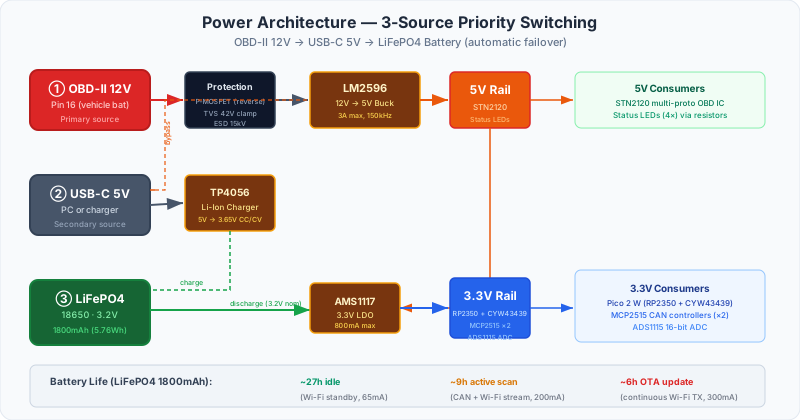
View text-based power diagram (accessibility)
┌─ POWER SOURCE PRIORITY (automatic switching) ─────────────────────┐
│                                                                    │
│  1. OBD-II Pin 16 (+12V Battery)                                   │
│       │                                                            │
│       ├── P-MOSFET (reverse polarity protection)                   │
│       ├── TVS Diode (42V transient clamp)                          │
│       └──→ LM2596 Buck Converter                                  │
│               ├──→ 5V Rail (STN2120, TP4056 bypass, ext sensor ref)│
│               └──→ 3.3V LDO (AMS1117-3.3)                         │
│                       ├──→ Pico 2 W (RP2350 + CYW43439)           │
│                       ├──→ MCP2515 CAN controllers (×2)            │
│                       ├──→ ADS1115 ADC                             │
│                       ├──→ microSD card (SPI)                      │
│                       └──→ Status LEDs                             │
│                                                                    │
│  2. USB-C (5V from PC / charger)                                   │
│       │                                                            │
│       ├──→ TP4056 Module (USB-C 5V 1A charge controller)           │
│       │       └──→ LiFePO4 18650 (3.2V 1800mAh, charges to 3.65V) │
│       └──→ 3.3V LDO → MCU + peripherals (when OBD-II absent)      │
│                                                                    │
│  3. LiFePO4 18650 Battery (3.2V nominal, 5.76Wh)                  │
│       │                                                            │
│       └──→ 3.3V LDO → MCU + peripherals (standalone portable)     │
│                                                                    │
│  Battery specs (BatterySpace LFP-18650-1800):                      │
│    Nominal: 3.2V  │  Capacity: 1800mAh  │  Energy: 5.76Wh         │
│    Charge: 3.65V  │  Cutoff: 2.5V       │  Max discharge: 5.4A    │
│    Cycles: 2000+ (100%DOD), 4000+ (80%DOD)                        │
│    Temperature: -20°C to +65°C (discharge)                         │
│    Dimensions: 18.15mm × 65.2mm  │  Weight: 45g                   │
│                                                                    │
│  Voltage divider → ADS1115 Ch0 (battery voltage monitor)           │
│                                                                    │
│  Total current draw:                                               │
│    Sleep:      ~15 mA  (RP2350 dormant + BLE advertising)          │
│    Idle:       ~65 mA  (RP2350 light sleep + CAN standby)          │
│    Active:     ~200 mA (Wi-Fi TX + dual CAN + ADC sampling)        │
│    Active+SD:  ~230 mA (Active + microSD write + ext sensor read)  │
│    Peak:       ~300 mA (OTA update + full CAN bus traffic)         │
│                                                                    │
│  Battery life (1800mAh at 3.2V):                                   │
│    Idle standby:   ~27 hours                                       │
│    Active scan:    ~9 hours                                        │
│    Active + log:   ~7.8 hours                                      │
│    Continuous OTA: ~6 hours                                        │
└────────────────────────────────────────────────────────────────────┘
Signal Flow — How Data Gets From the Vehicle to Your Phone
External Sensor Data Path
External sensor data is merged into the same data stream as OBD-II PIDs. Log wideband AFR alongside RPM and boost pressure in one synchronized session. No separate gauge, no separate app.
Scanner ↔ App Communication
Wi-Fi Mode (Primary)
Scanner creates a soft AP (SSID: CEH-SCAN-XXXX) or joins your home network. CYW43439 radio on the Pico 2 W communicates over WebSocket on port 8080.
BLE Mode (Mobile)
BLE 5.2 GATT service via CYW43439 for phones. Lower throughput than Wi-Fi but uses less power and auto-reconnects.
PCB Layout — Component Placement
Top-view rendering of the 4-layer FR4 board (85×55mm). All components are surface-mount except the OBD-II connector, USB-C port, microSD socket, JST sensor header, and 18650 battery holder.
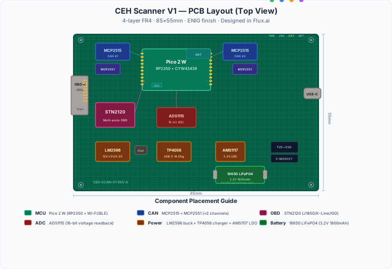
PCB Design & Prototyping Tools
🛠 Flux.ai — PCB Design
The CEH Scanner PCB is designed in Flux.ai — a browser-based AI-powered ECAD tool with live component sourcing, auto-routing, and direct export to JLCPCB/PCBWay for manufacturing.
| Board | 4-layer FR4, ENIG finish, 85×55mm |
| Fab Partner | JLCPCB (5-day turnaround, $2–4/board at 1K qty) |
| Format | Exports Gerbers, drill files, BOM, pick-and-place |
| Collaboration | Real-time multi-user, version control, design reviews |
Why Flux over KiCad/Altium? Browser-native means no install, AI assists with routing and component selection, and the BOM auto-updates with live pricing from DigiKey/Mouser/LCSC. Open schematics are forkable — anyone can clone and modify the design.
🎮 Wokwi — Firmware Simulation
Before burning firmware to silicon, we prototype in Wokwi Pi Pico Simulator — a browser-based hardware simulator that runs MicroPython and C/C++ Pico SDK code on a virtual RP2350.
| Supports | Pi Pico, Pico W, Pico 2 W (RP2350) |
| Languages | MicroPython, C/C++ (Pico SDK), Arduino |
| Peripherals | SPI, I2C, UART, PIO, ADC, PWM — all simulated |
| Community | 171K+ projects, templates, shared circuits |
Simulation lets us test CAN protocol parsing, ADC voltage reading, and Wi-Fi WebSocket communication without physical hardware. The firmware is CI-tested against Wokwi before OTA deployment to real scanners.
Design Principles
🛠 Right to Repair
Full schematics published. No proprietary connectors. Standard OBD-II. USB-C for updates. The hardware is yours — we publish everything so you can verify, modify, or build on it.
🔒 Software Tiers, Not Hardware Locks
Every scanner ships with the same PCB, same components, same firmware base. Your subscription tier unlocks features in software. No different SKUs, no hardware dongles, no artificial limitations burned into silicon.
📈 Automotive-Grade Protection
Reverse polarity (P-MOSFET), 42V transient suppression (TVS), 15kV ESD protection, -20°C to +65°C battery-safe operating range. LiFePO4 chemistry chosen specifically for underhood thermal extremes — no swelling, no thermal runaway.
🌐 OTA Updates Forever
Firmware updates over Wi-Fi, USB-C, or microSD card. New vehicle coverage, protocol improvements, PID libraries, and feature unlocks — all without shipping new hardware. Three update paths means you're never stuck with outdated firmware.
🔋 Cordless Operation
On-board LiFePO4 18650 battery (3.2V, 1800mAh) lets you start scanning before turning the key — read stored DTCs, review freeze frames, and stream live data without vehicle power. Charges from OBD-II 12V or USB-C. ~27 hours idle, ~9 hours active scanning, ~6 hours continuous OTA.
Market Context: Professional OBD-II Tools
We studied the professional OBD-II diagnostic tool market to understand the feature landscape and identify opportunities. Here's how the major product categories compare:
OBD-II Gauge + Tuner Category
~$300–$400 · Products like the nGauge®
Strengths: Manufacturer-specific PID packs, external sensor inputs (wideband O2, EGT), microSD firmware updates.
Limitations: Built-in display limits screen real estate. PID packs require manual SD card updates. No wireless data streaming or cloud-based analysis.
OBD-II Data Logger + Gauge Category
~$400–$600 · Products like the nDash™
Strengths: Performance measurement (1/4 mile, 0-60), data logging to SD card, custom calculators, PC companion tool for analysis.
Limitations: Data logging requires pulling the SD card and importing to a PC. No wireless real-time streaming. Performance timer is standalone without correlation to other OBD-II data streams.
Professional Data Logger Category
~$800+ · Products like the DashDAQ™ XL
Strengths: Multi-channel recording, OBD-II + optional modules for vintage vehicles. Highly regarded as a professional data logging platform.
Limitations: Requires a laptop tethered via USB for live viewing. No wireless streaming capability. Higher price point limits accessibility for independent shops and DIY users.
All product names, logos, and trademarks are the property of their respective owners and are used here solely for identification and comparison purposes. nGauge® is a trademark of Patriot Diagnostics. nDash™ and DashDAQ™ are trademarks of Drew Technologies. OBDLink® is a registered trademark of ScanTool.net. Check Engine Help is not affiliated with, endorsed by, or sponsored by any of these companies. Feature details based on publicly available product documentation.